Follow

How to Add a Second (Failover) Internet Uplink

Click on the green button below, corresponding to your UTM software version
Version 2.5 Versions 3.0 & 5.0

Applies to Platform: UTM 2.4, UTM 2.5, 4i Edge 2.5
Last Updated: 08 May 2014

Applies to Platform: UTM 3.0, 4i Edge 3.0, UTM 5.0, 4i Edge 5.0
Last Updated: 08 May 2014

This lesson will illustrate the necessary steps to configure a second Internet uplink on a typical Endian Appliance. Adding a second uplink can prove useful on two typical scenarios: On the one side, to configure a default WAN failover policy should the primary Internet (RED) connection go down, on the other side the seond uplink can be used together with the main uplink to set up an outbound load-sharing (policy routing) to distribute outgoing traffic among the two Internet circuits.

Create Additional Uplink

?name=media_1302732947601.png uplink1.png

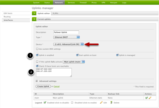
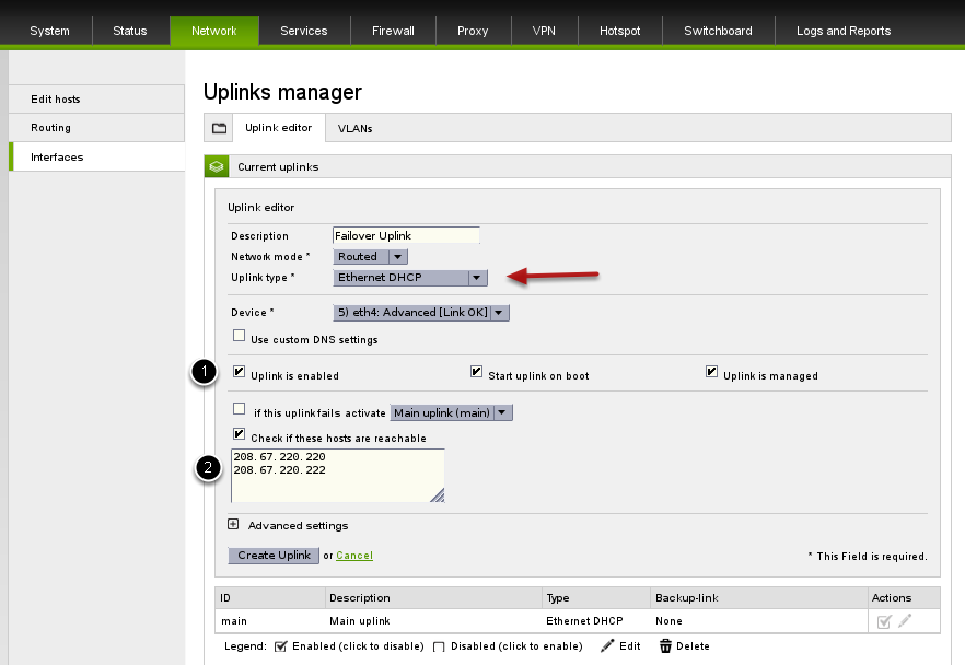
To create an additional uplink, go to Network > Interfaces and click "Create an Uplink". From here you can select the type of uplink (Ethernet Static/DHCP, ADSL, etc.) and then provide the appropriate configuration settings. Make sure you provide a valid unused physical Ethernet interface for "Device". Also ensure you (1) have all 3 checkboxes selected and that you (2) activate real-time Internet availability checking by selecting "Check if these hosts are reachable" and then provide some public and reliable (always responsive) IP addresses.

Click Create Uplink when your done.

Warning

It's recommended to only use IP addresses and not DNS names for reachable check hosts (2) as this will ensure a higher degree of accuracy and remove any potential DNS resolution issues.

Warning

It is fundamental to avoid putting same IP addresses as reachable check hosts (2) in different uplink.

For example, the following configuration is not correct as 1.1.1.1 is in common with both uplink:

main: 1.1.1.1, 208.67.222.222

uplink1: 1.1.1.1, 208.67.220.220

while the following one is fine as all IP addresses are different between the two uplinks:

main: 1.1.1.1, 208.67.222.222

uplink1: 1.1.1.0, 208.67.220.220

Now, depending on the type of scenario you want to deploy, either go to the next section to setup a failover uplink or follow this howto to set up policy routing.

Configure Main uplink Failover Policy

?name=media_1302734006516.png

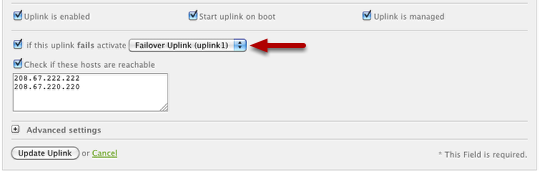
Now you must edit your Main Uplink (primary) to use the secondary uplink as the failover. You can do this by editing your Main Uplink and then ensure you have a configuration options similar to what is shown above.

Have more questions? Submit a request

Comments