Applies to Platform: UTM 2.5, 4i Edge 2.5
Last Update: 27th of August 2013
This lesson will illustrate the necessary steps to configure a very simple Net-to-Net IPSec VPN tunnel between an Endian (v2.5) appliance and a Cisco firewall (PIX / ASA / FWSM).
Note
(1) Select which Internet interface you want to use for this specific connection
(2) Provide the public IP or hostname of the remote VPN device (4.4.4.1)
(3) Edit the local Green subnet (if necessary)
(4) Provide the remote VPN subnet to connect to (172.16.15.0/24)
(5) Provide an authentication method. In this case we're using pre-shared key as this is the simplest and most common method.
We'll leave the advanced encyption and IKE settings as default.
Click Save to finish.
Cisco VPN Wizard (Site B)

For the Cisco side we'll be using the graphical ASDM (version 6.1) administration tool. For convenience, we'll use the built-in VPN wizard found under Wizards > IPSec VPN Wizard.
Add a VPN Tunnel Type (Site B)
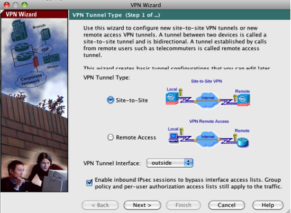
The first step is to select the "Site-to-Site" VPN Tunnel type and we’ll use the default outside interface for our connection.
Click Next button to continue.
Configure the VPN Peer (Site B)
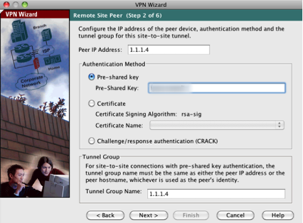
The next step is to configure the remote peer IP address (remote VPN endpoint) and provide the pre-shared key for the connection (configured earlier). The ‘Tunnel Group Name’ should be either the IP address or hostname of the remote VPN connection and should match on both endpoint devices of the VPN tunnel.
Click Next button to continue.
Configure IKE Policy (Site B)
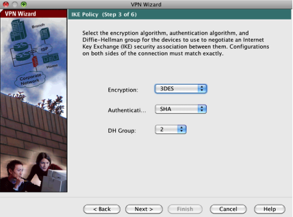
Next, we can configure the IKE policy where we’ll just use the defaults as those match up with our Endian default settings.
Click Next button to continue.
Configure Encryption and Authentication (Site B)
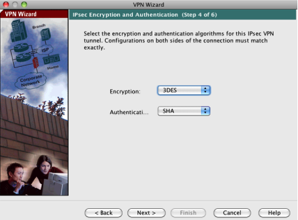
Now we can configure the IPSec Encryption and Authentication policy which (again) we’ll use the defaults to match up with our Endian.
Click Next button to continue.
Configure VPN Networks
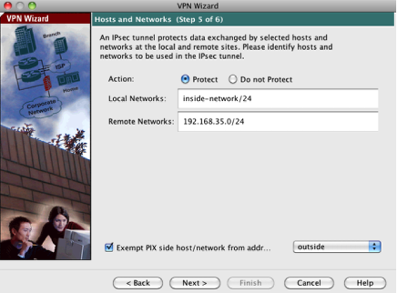
Next, we’ll configure which networks are being protected on either side of the tunnel and apply a NAT exemption policy to any intra-VPN traffic. For the ‘Local Network’ we’ll select the 172.16.15.0/24 subnet which is aliased as our inside-network. For the remote network, we’ll use the Endian Green (LAN) IP range of 192.168.35.0/24. We’ll keep the VPN traffic exempt from NAT on the outside interface.
Click Next button to continue.
VPN Wizard Confirmation

The very last step is a confirmation window with all of the relevant VPN information to confirm before finishing the VPN connection setup process.
Click Finish button to save your configuration
Cisco Firewall ACL

The last step with the Cisco firewall is to ensure we have an appropriate access policy (ACL) to allow traffic from the internal Cisco LAN to the Endian Green (LAN). We can do this by going to ‘Configuration > Firewall > Access Rules’ and adding a rule to the inside interface. In this example, we’re creating a rule to allow all traffic (service = ip) between the two protected networks.
Verify Connection (Site A & B)

On the Site A VPN device, you should the "Status" go from CLOSED to OPEN which indicates a successful connection. You should also similarly be able to see a successful VPN connection within the ASDM administrative console as well.
Test VPN Connectivity (Site A & B)
Now you should be able to successfully test all internal access to remote devices (resources) from both sides of the VPN tunnel. Anything from a simple ICMP ping to an RDP session or remote web server should be accessible across the tunnel.
Comments